This is video tutorial is for users new to LogicWorks. It demonstrates how to build and simulate a simple circuit.
This video tutorial provides instruction on how edit a circuit.
Check out this interesting project that was done by two students at California State University, East Bay. As part of their final project for their computer architecture coarse they used LogicWorks to simulate a three stage MIPS processor.
https://github.com/jeffreymcclain/Computer-Architecture-Project


Help customers find the products they need with Big Zeta Search, a B2B company search, electronic part search, parametric search and keyword search tool.
Check out Big Zeta’s website for more information.
This tutorial is divided into a number of sections, allowing you to review the basic functions first and then learn abut more advanced features. The first section is entitled “The Five-Minute Schematic and Simulation” and will give you a taste of how quickly you can put together a circuit with full simulation. The later sections are divided by subject, so that you can study in greater detail the features that are important for you application.

PEI-Genesis is a leading global provider of custom engineered connector and cable solutions. They provide Custom Engineered Connector & Cable Interconnect Solutions for any project you may have.
Logic Gates with LogicWorks Part 1 by Hartechworld
Intro to LogicWorks by James Tandon
UZHCT109 Logic Works Tutorial Decade Counter by Remeo A Shava
Introduction to Sequential Logic in LogicWorks by Ricky Castles
Building an Up and Down Counter in LogicWorks 5 by Ricky Castles
CS 202 Lecture 15 – LogicWorks Subcircuits by cs461middlebury
Purpose of This Note
This DesignNote describes how to create a title block on a DesignWorks Professional schematic. Using a graphics item to show the fixed elements of the title and “text variables” for the changing elements, you can make a title block that can be used for any of your designs without modification.
Most of what is included here is condensed from the chapter “Advanced Schematic Editing” in the DesignWorks manual.
Introduction
DesignWorks has a number of features which can assist in creating title blocks which will contain information that is automatically updated when the title block is used on new pages or in new designs. A simple title block can be created using the random text feature. Click the pencil cursor in the desired location on the diagram and enter the desired text. After the text has been typed, click on the text block to select it, then use the Get Info command to set the text size appropriately and create a frame.
IMPORTANT NOTE: In many schematic packages, it is common practice to create a the block as a device symbol, save it in a library and place it on the diagram in the usual way. It is possible to create a title block this way in DesignWorks, but we don’t recommend it for a couple of reasons. One is that this creates an extra device symbol that can confuse netlists and bills of materials if you don’t mark it correctly. Secondly, this does not allow you to take advantage of the text variable feature that will automatically update page titles, dates, etc. on the title block.
A more striking title block can be created using a graphic item imported from the device symbol editor, such as the following:
You can then place text items containing text variables on top of this block to create a complete, auto-updating title block.
Steps to Create a Title Block and Template Design
Here are the specific steps to create a template design containing your title block:
- Create a new, empty design using any existing template or settings that are appropriate for your needs.
- Delete any existing border or title block items that are not appropriate. Background objects can be selected by holding the Shift and Control keys (Windows) or Command and Option keys (Mac) while clicking on them.
- Draw the title block, showing only the fixed text and graphic items that will be the same for all designs, like the example above. You can use the built-in device symbol editor or use an external graphics application.
- If you use the device symbol editor (DevEditor), DON’T save the title block to a library and place it as a device, for the reasons noted above. DO use the Select All command and then Copy the graphic, switch to your schematic and Paste it onto the schematic. This places the item as a “miscellaneous graphic” instead of as a device.
- If you use an external application, please note a couple of limitations:
- DesignWorks for Windows version 3 only accepts bitmap graphics from other applications. This means that all external graphic items are reduced to screen resolution and may not print smoothly. Version 4 added the ability to handle Enhanced Metafile Format, so this limitation no longer applies, as long as you use an external application that produces this format (for example, Microsoft Word or Corel Draw).
- DesignWorks for Macintosh uses the standard Mac PICT or PICT2 formats to place graphics on the diagram. If you use recent version color graphics application, this data will be placed in PICT2 format, which is NOT portable to the Windows version. If you need to ensure portability, use only graphics that can be created in the device symbol editor.
- Set the title block graphic to be a background and border object using the Get Info command. Once it has been converted to a background object, it will not be selected again and you can use text notations to draw on top of it. Text variables can be used to add dates and titles to the block.
- Use the text tool to place individual text items on top of the title block, using text variables where desired. Here are some of the more popular text variables (see “variables” in the manual index for the complete list):$DATEMODIFIED – The date the file was last modified
$NUMPAGES – The total number of pages in the circuit
$PAGENUM – The number of this page
$PAGETITLE – The title of this page
&anything – An ampersand character followed by an attribute field name substitutes the value of that design attribute field. E.g. &Designer will substitute the contents of the Designer design attribute field, so that you can set it once and it will automatically update all pages. - Set all text items to be “border” and “background” using the Get Info command (shortcut: right-click (Windows) or Cmd-click (Mac) on each item to change settings).
- Save the design. In DesignWorks Professional 4 for Windows, you can save the design into your templates directory (normally called Templates by default) and it will appear in the template list when you create a new design. In DesignWorks Professional 4 for Macintosh, you can place the template in the templates folder for the current design kit. In version 3, you can either use the new design as a starting point for each design, or use the Import Sheet Info command to import the border items.
The completed title block with text variables might look like this (note that you will never see it this way because DesignWorks substitutes the values for the variables as soon as you finish typing):
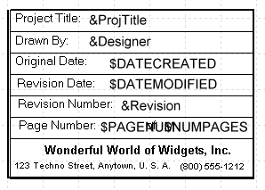
Note that the $PAGENUM and $NUMPAGES items appear to run onto one another, but will update correctly when substituted with the smaller numeric value.
Here are some additional related notes that may be helpful:
- The “background” and “border” settings have related but different meanings. “Background” means that the object cannot be selected by simply clicking on it (see below). “Border” means that the object is considered to be part of the sheet border and will be copied automatically when the circuit is used as a template or new pages are created. Title block items should normally have both these settings ON.
- Background objects can be selected by holding the Shift and Control keys (Windows) or Command and Option keys (Mac) while clicking on them.
- To change design attribute values, select the Design Attributes command in the Options menu.
- The “Designer” and “Revision” design attribute fields are built in to DesignWorks. You can add additional fields as needed using the Define Attribute Fields command. Just remember to check the “Design” item under “allowed object types”.
Example Circuit
http://www.designworkssolutions.com/wp-content/uploads/title_block.zip
This video demonstrates how to use LogicWorks for the Mac as a front end to MacSpice. MacSpice is an analog simulator and is available free from http://www.macspice.com
- 1
- 2