Home › Forums › Technical Notes › Device and Signal Naming in Hierarchical Designs
- This topic has 0 replies, 1 voice, and was last updated 9 years, 9 months ago by
 NeilMackenzie.
-
AuthorPosts
-
July 30, 2014 at 9:08 pm #808
 NeilMackenzieKeymaster
Device and Signal Naming in Hierarchical Designs
Purpose of This Note
This DesignNote describes the various ways of identifying objects in hierarchical designs and helps you choose the appropriate method for your application.
This note applies to: Windows Macintosh DesignWorks Professional 3.0 + 3.0 + DesignWorks Lite N/A N/A LogicWorks N/A N/A Notes: N/A – not applicable to this version. “3.0 +” indicates version 3.0 and later. Since this note may apply to multiple versions and platforms, there may be some variation in exact configuration of menu commands and screen layouts from that shown in this note, but the same principles
apply.Introduction
DesignWorks Professional provides full facilities for creating hierarchical designs, i.e. designs in which a symbol on a circuit diagram can itself represent another nested circuit block.
In non-hierarchical (“flat”) designs, identifying physical devices is quite simple since there is a one-to-one correspondence between symbols on the schematic and physical devices. In flat designs, DesignWorks normally identifies devices by placing a unique “name” or “reference designator” in the Name attribute field. This name can be automatically or manually assigned and can be used in netlists to uniquely identify the device to PCB layout or simulation packages.
In hierarchical designs, identifying objects is a bit trickier for a number of reasons:
- One symbol in a subcircuit may actually represent multiple physical devices. For more explanation of this, see the following example.
- A physical board-level name (such as “U23”) doesn’t give the designer any idea which subcircuit block the object is located in, making navigation trickier in large designs.
- The PCB layout or simulation system that is receiving netlist data from the schematic may have limitations or special requirements for naming.
The following sections describe the options available in DesignWorks for naming objects in hierarchical designs.
Example
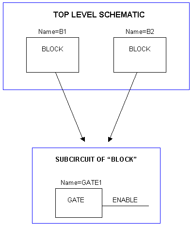
 Suppose you have created a symbol called BLOCK and defined a subcircuit for it containing a single device called GATE1 (specifically, its Name attribute contains “GATE1”). The subcircuit also has a signal that isn’t connected to the outside world called ENABLE (again, this means its Name attribute is “ENABLE”).
If your top level schematic contains two copies of BLOCK (call them B1 and B2), then your design physically has two GATE1’s and two signals ENABLE. If you need to generate a flat netlist for PCB or simulation, you need to come up with a name that uniquely identifies each physical item. There are two common ways of doing this:
1) You can use a “hierarchical name”, i.e. a name made by concatenating the names (i.e. the Name attributes) of the nested blocks down to the individual item, in this case the physical devices would be B1/GATE1 and B2/GATE1 and the signals would be B1/ENABLE and B2/ENABLE. The report generator will produce this kind of name using the $SIGHIERNAME and $DEVHIERNAME commands and you can change the “/” to whatever separator you want. The advantages of using a hierarchical name are: You don’t need to run around to each physical item and assign a name, no “instance data” (i.e. InstName) needs to be stored, and the name gives you a clear path to where that item is in the design. The disadvantages are: The names are arbitrarily long and contain strange characters (so the PCB system may not accept them) and they bear no information about the physical location on the board (i.e. you don’t get the U1, U2, etc that board and test people like). This scheme uses only Name attributes and requires no instance data, so you can do it entirely in Pure hierarchy mode.
2) You can assign an “instance name” to each physical item. In this case the schematic
package has to keep track of each possible path that can burrow down to a specific device and has to keep a separate copy of the instance information. In the simple case above, the signal ENABLE has two sets of instance data associated with it. This is what Physical hierarchy mode does. In this case, you would typically use the Name field to provide a “logical” name for each item (like “GATE1”) and then use the InstName field to assign the physical package or signal name. Once you have assigned unique InstNames to items, you can’t switch back to Pure mode, because you are telling the schematic package to keep only one set of definition data for each block and it discards the instance data.The bottom line on all this is that it depends on what you’re trying to get out the end.
For board level hierarchical designs, here is the typical scheme:- Do the initial design in Pure mode using only the Name field to assign logical names to all items. The logical name is something that may describe the function of each component, but does not reflect its physical location on the board. The logical name need only be unique within its circuit block.
- Switch to Physical mode and use the gate packager or manually assign package names (e.g.U1, U2…) to each physical component. Most board designers and test people don’t find names like B1/GATE1 to be very cool.
- Use hierarchical names for signals. Going around and assigning instance names to all the signals is a hassle and they are less important because signal names are not usually a big issue once the board is built.
Once instance names have been assigned, you can never go back to Pure mode or you will lose them all. If you want to go back to Pure mode because it makes the editing easier, you could actually come up with a script that would write out all the instance data to a text file and another one that would “back annotate” it back into the design later if you wanted, however this is not a built-in function of DesignWorks and would require some development.
Note that the report generator can only produce “flattened” netlists in Physical mode. If you have a Pure design and you want a flattened netlist, you have to switch it over temporarily to give the report generator somewhere to keep its temporary data while it flattens.
Attachments:
-
AuthorPosts
 Suppose you have created a symbol called BLOCK and defined a subcircuit for it containing a single device called GATE1 (specifically, its Name attribute contains “GATE1”). The subcircuit also has a signal that isn’t connected to the outside world called ENABLE (again, this means its Name attribute is “ENABLE”).


- You must be logged in to reply to this topic.